TM 1-1520-238-23
5-278
5.64.
TAIL ROTOR FORK LOCKING PLATE DISASSEMBLY/ASSEMBLY (AVIM) – continued
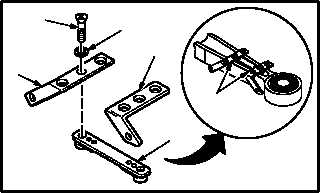
5.64.6. Installation
NOTE
Clamp plates must be alined perpendicu-
lar (90 degrees) to locking plate when
assembled. Do not allow clamp plates or
locking plate to shift when installing or
torquing screws.
a. Install plates (2) and (3) on locking plate (1).
Torque screws (4) to 25 INCH-POUNDS.
(1) Position plates (2) and (3) on locking plate (1)
and aline 90 degrees perpendicular to locking
plate (1).
(2) Install two screws (4) and washers (5).
(3) Torque screws (4) to 25 INCH-POUNDS. Use
torque wrench, screwdriver bit holder, and
screwdriver bit.
b. Inspect (QA).
c. Install tail rotor fork clamp and locking plate
(para 5.63).
END OF TASK
M04-3825-2
4
2
5
3
1
90º