TM 1-1520-238-23
4-214
4.66.
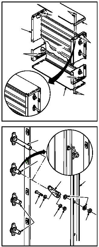
NO. 1 OR NO. 2 ENGINE LOUVER DISASSEMBLY/ASSEMBLY (AVIM) – continued
b. Install two endplates (22) and (23) on chan-
nels (24) and (25).
(1) Aline rivet holes on endplates (22) and (23)
with rivet holes on channels (24) and (25).
Install rivets (28) through endplates (22) and
(23)
and
channels
(24)
and
(25)
(TM 1-1500-204-23).
(2) Install four nutplates (27) on channel (25) and
endplates (22) and (23) (TM 1-1500-204-23).
(3) Install four nutplates (26) on channel (24) and
endplates (22) and (23) (TM 1-1500-204-23).
c. Install linkage channel (17).
(1) Install lever (13) on vane shaft (2).
(2) Aline hole on lever (13) with hole in vane shaft
(2).
(3) Install screw (18) through washer (21), lever
(13), and shaft (2).
(4) Install washer (20) and nut (19).
(5) Repeat steps c.(2) thru c.(5) for other six lev-
ers (13) and shafts (14).
(6) Install seven washers (16) on levers (13).
(7) Aline holes in channel (17) with control lever
(13).
(8) Install seven washers (16) and new push-on
nuts (15) on levers (13).
NOTE
Vanes must move without binding or
dragging. If binding or dragging occurs,
go to paragraph 4.66.3 and repeat steps
c. and d. Then go to paragraph 4.66.6
and repeat steps a. and b.
GO TO NEXT PAGE
M04-3374-9
22
26
24
28
27
25
27
23
26
28
2
14
13
16
15
19
20
21
18
17
MO4-3374-6
14