TM 1-1520-238-23
5-158
Change 8
5.33.
MAIN ROTOR BLADE LEAD LAG LINK REMOVAL/INSTALLATION
5.33.1. Description
This task covers:
Removal. Cleaning. Inspection. Installation.
5.33.2. Initial Setup
Tools:
Aircraft maintenance tool kit (item 372, App H)
0.000 - 6.000-inch outside micrometer caliper set
(item 52, App H)
0.300 - 24/0 - 24-inch inside/outside vernier caliper
(item 54, App H)
Pitch Case Housing Lead Lag Link/strap
Pack Alignment Tool (Figure 475, App D)
Pitch Case Housing Lead Lag Link/strap
Pack Alignment Tool (Figure 476, App D)
Materials/Parts:
Cloth (item 52, App F)
Personnel Required:
68D
Aircraft Powertrain Repairer/NDI
One person to assist
67R3F
Attack Helicopter Repairer/Technical
Inspector
Equipment Conditions:
Ref
Condition
1.57
Helicopter safed
5.23
Main rotor damper disconnected from lead
lag link
5.32
Main rotor lead lag link bearing retainer and
hub bearing removed
WARNING
FLIGHT SAFETY PART
The main rotor lead lag link is a flight
safety part. Failure to follow
maintenance instructions may result
in serious injury or death of
crewmembers and/or serious damage
to the helicopter.
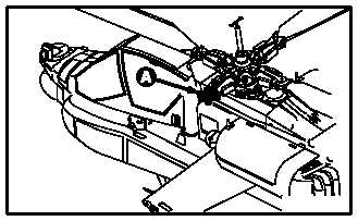
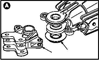
5.33.3. Removal
a. Support pitch housing (1) and pull lead lag
link (2) from housing (1).
5.33.4. Cleaning
a. Wipe pitch housing, exposed strap pack, and
lead lag link. Use cloth (item 52, App F).
GO TO NEXT PAGE
M04–228
–4
M04–228
1
2
1