TM 1-1520-238-23
Change 3
5-159
5.33.
MAIN ROTOR BLADE LEAD LAG LINK REMOVAL/INSTALLATION – continued
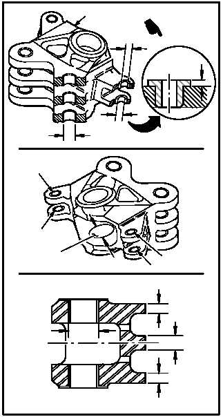
5.33.5. Inspection
a. Check pitch housing and exposed strap pack
for wear and damage (para 5.1).
b. Check lead lag link (2).
(1) Check ID of blade attach lug bushings (3)
(6 places). ID not to exceed 1.066 INCH. Use
caliper.
(2) Check ID of lower damper attach lug flanged
bushings (4) (2 places). ID not to exceed
0.7557 INCH. Use caliper.
(3) Check flange thickness of lower damper at-
tach lug flanged bushings (4) (2 places).
Thickness shall not be less than 0.050 INCH.
Use caliper set.
(4) Check ID of upper damper attach lug flanged
bushings (5) (2 places). ID not to exceed
0.9572 INCH. Use caliper.
(5) Check thickness of upper and lower blade
attach flanges (6) (4 places). Thickness shall
not be less than 0.790 INCH. Use caliper set.
(6) Check thickness of center blade attach
flanges (7) (2 places). Thickness shall not be
less than 0.690 INCH. Use caliper set.
NOTE
If center pivot Teflon liners are installed,
perform steps (7) thru (9). If center pivot
sleeve bearings are installed, perform
steps (10) thru (12).
(7) Check ID of upper and lower holes (8). ID not
to exceed 2.536 INCH. Use caliper.
(8) Check Teflon liners (9) for evidence of liner
to-metal penetration at any point. None al-
lowed.
(9) Check Teflon liners (9) for evidence of de-
bonding. None allowed.
GO TO NEXT PAGE
2
5
4
3
M04–228–
5A
4
5
5
4
6
7
8
6
9
0.05
0
8