TM 1-1520-238-23
5-160
Change 8
5.33.
MAIN ROTOR BLADE LEAD LAG LINK REMOVAL/INSTALLATION – continued
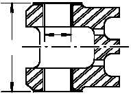
(10) Check ID (10) of upper and lower sleeve
bearings (11) (2 places). ID not to exceed
2.503 INCH. Use caliper. Replace bearings
(para 5.33A).
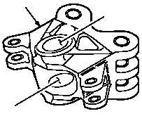
(11) Check sleeve bearings (11) for evidence of
bearing-to-metal penetration at any point.
None allowed. Replace bearings (para
5.33A).
(12) Check distance (12) between upper and low-
er sleeve bearing (11). Dimension not to ex-
ceed 5.560 INCH. Use caliper set. Replace
bearings (para 5.33A).
(13) Check sleeve bearings (11) for looseness.
None allowed. Replace bearings (para
5.33A).
c. Check link for cracks. None allowed.
d. Check link for corrosion (para 1.49).
e. Check link (2) for nicks, gouges, and
scratches.
(1) Depth up to 0.005 INCH must be blended
(blend ratio 10:1).
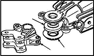
5.33.6. Installation
a. Install link (2) on housing (1).
(1) Support housing (1).
(2) Case Housing/Lead Lag Link and strap pack
alignment tool (Fig 475, App D). Align link (2)
with strap pack (13) and housing (1).
b. Install main rotor lead lag link bearing retainer
and bearing (para 5.32).
c. Install main rotor damper (para 5.23).
d. Inspect (QA).
END OF TASK
M04–228
7
10
11
11
12
2
M04–228
6
2
1
13