TM 1-1520-238-23
6-69
6.11.
NO. 5 TAIL ROTOR DRIVE SHAFT, DAMPER, AND ANTI-FLAIL SUPPORT
REMOVAL/INSTALLATION – continued
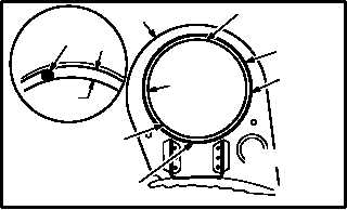
g. Adjust support (5) to achieve minimum clear-
ances of 0.150 INCH at 6, 9, and 12 o’clock
positions and 0.220 INCH at 3 o’clock position
between shaft (10) and support sleeve (26).
Torque seven screws (6) to 20 INCH-POUNDS.
NOTE
Minimum clearance shall be measured
between outside diameter of drive shaft
and inside diameter of anti-flail support
bearing sleeve.
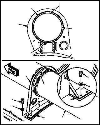
(1) Adjust support (5) and obtain minimum clear-
ance of 0.150 INCH at 6 and 12 o’clock posi-
tions between shaft (10) and sleeve (26).
(a) Measure and record existing clearance at
6 and 12 o’clock positions between shaft
(10) and sleeve (26). Use inspection
gage.
(b) Remove screws (6) and washers (7).
(c) Remove or add shims (8) and (9) equally
to obtain minimum clearance of 0.150
INCH at 6 and 12 o’clock positions be-
tween shaft (10) and sleeve (26). Use
inspection gage.
(d) Hand tighten screws (6) and washers (7).
(e) Slowly rotate shaft (10).
(f) Measure and verify minimum clearance
of 0.150 INCH at 6 and 12 o’clock posi-
tions between shaft (10) and sleeve (26)
while shaft (10) is rotating. Use
inspection gage.
GO TO NEXT PAGE
0.150 OR
0.220
10
26
REAR VIEW
12
O'CLOCK
0.150 MIN.
9
O'CLOCK
0.150 MIN.
6
O'CLOCK
0.150 MIN.
INSPECTION
GAGE
M04-0447-21
3
O'CLOCK
0.220 MIN.
5
M04-0447-14
REAR VIEW
12 O'CLOCK
0.150 MIN.
6 O'CLOCK
0.150 MIN.
9
6
7
6
7
5
8
5
26
10
10
26