TM 1-1520-238-23
7-367
7.94.
UTILITY HYDRAULIC RETURN ACCUMULATOR REMOVAL/INSTALLATION – continued
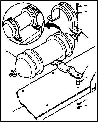
c. Install accumulator (2) on bracket (5).
(1) Aline four spacers (11) and mounting holes of
bottom halves of two clamps (10) with mount-
ing holes in bracket (5).
(2) Position accumulator (2) on bottom half of
two clamps (10).
(3) Position top halves of two clamps (10) on
accumulator (2). Aline mounting holes.
(4) Install four screws (8) through four washers
(9), clamps (10), spacers (11), bracket (5),
and washers (7).
NOTE
Do not tighten locknuts until the nitrogen
manifold tube is installed.
(5) Install four new locknuts (6) finger tight.
d. Install utility hydraulic return accumulator ni-
trogen manifold tube (para 7.97).
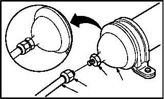
e. Install tube (1) on accumulator (2).
(1) Lubricate threads of reducer (4). Use clean
hydraulic fluid (item 92, App F).
(2) Install nut (3) on reducer (4).
f. Inspect (QA).
g. Service utility hydraulic return accumulator
(para 1.37).
h. Bleed utility hydraulic system (para 1.35).
i. Service utility hydraulic system (para 1.34).
j. Perform utility hydraulic system maintenance
operational check (TM 1-1520-238-T).
k. Install access fairing L175 (para 2.2).
END OF TASK
M04-3297-5
8
9
10
10
11
7
6
5
2
M04-3297-7
2
4
3
1