TM 1-1520-238-23
7-439
7.113.
HYDRAULIC TUBES AND FITTINGS PERMASWAGE REPAIR – continued
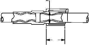
c. Inspect swaged fitting with appropriate go/no-
go gage. Gage must fit around OD of fitting di-
mension A. Gage shoulder must contact fitting
end while covering minimum acceptable length of
fitting dimension B. Fitting shall meet dimensional
requirements of table if proper gage is not avail-
able.
NOTE
All dimensions in inches.
Tube
DIA
Dimension B
Min Swaged Lgth
Dimension A
Max Swaged Dia
Go-No-Go
Gage
1/4
(-4)
0.460
0.315
D12 9892-4
3/8
(-6)
0.530
0.447
D12 9892-6
1/2
(-8)
1.020
0.606
D12 9892-8
5/8 (-10)
1.020
0.735
D12 9892-10
3/4 (-12)
1.020
0.863
D12 9892-12
1 (-16)
1.160
1.144
D12 9892-16
1-1/4 (-20)
1.406
1.390
D12 9892-20
1-1/2 (-24)
1.420
1.680
D12 9892-24
d. It is permissible and advised to reswage fit-
tings to meet proper swage dimensions. No
extensive reduction in fitting diameter beyond
specified tolerance limits can occur if proper up-
per and lower die blocks are used.
e. Inspect (QA).
f. Bleed primary and utility hydraulic systems
(para 1.35).
g. Service primary and utility hydraulic systems
(para 1.34).
h. Perform hydraulic system leak check (para
7.2).
i. Install access panels (para 2.2).
END OF TASK
M04-2844-21
A
B