TM 1-1520-238-23
7-434
7.113.
HYDRAULIC TUBES AND FITTINGS PERMASWAGE REPAIR – continued
7.113.9. Swage Tube
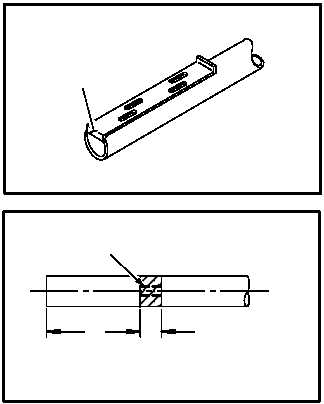
a. Mark tube end with tool D9862. Use slot
marked with tube size dash number. Place lip
stop (16) against end of tube as shown. Using slot
as guide, mark tube on two places 180 degrees
apart with marking pen. See table for tube inser-
tion band marking, if marking tool D9862 is not
available.
TUBE INSERTION BAND MARKING (IN.)
Tube
Size
Minimum
Tube
Insertion
Maximum
Tube
Insertion
1/4
(-4)
0.615
0.915
5/16
(-5)
0.655
0.955
3/8
(-6)
0.690
0.990
1/2
(-8)
1.193
1.493
5/8
(-10)
1.233
1.533
3/4
(-12)
1.303
1.603
1
(-16)
1.448
1.748
1-1/4
(-20)
1.550
1.850
1-1/2
(-24)
1.675
1.975
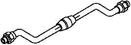
b. Position prepared tube in fitting. Aline mating
ends. Check to see if swaging at separable fitting
can be done if installed on aircraft. If not, mark
fitting and tube so proper clocking is obtained.
Position and attach separable end fitting to com-
ponent if swaging is done on aircraft. Aline fitting
mating ends. Torque end fitting to final torque,
making sure fixed portion of fitting is held station-
ary.
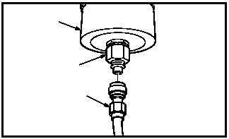
c. Connect hydraulic pressure line (17) from por-
table hydraulic power supply to quick discon-
nect fitting (18) on base of swaging tool (19).
GO TO NEXT PAGE
M04-2844-11
16
M04-2844-12
0.300 STRIPE WHEN USING
MARKING TOOL
A
0.300 MAX
MINIMUM
TUBE INSERTION BAND
M04-2844-14
M04-2844-15
18
17
19