TM 1-1520-238-23
6-95
6.16.
NO. 7 (APU) DRIVE SHAFT AND ANTI-FLAIL SUPPORT REMOVAL/INSTALLATION – continued
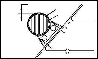
d. Check clearance between support (1) and
shaft (10) and adjust support (1) if necessary
to achieve minimum clearance of 0.026 INCH.
NOTE
Minimum clearance shall be mea-
sured between outside diameter of
drive shaft and inside diameter of anti-
flail support.
Minimum clearance of 0.026 INCH
must exist completely around drive
shaft.
(1) Insert gage between shaft (10) and support
(1). Check that clearance of 0.026 INCH or
greater exists completely around shaft (10).
Use gap setting gage.
NOTE
If minimum clearance of 0.026 INCH be-
tween anti-flail support and drive shaft
exists, skip step d.(2) and go to step e.
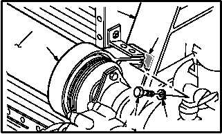
(2) Adjust support (1) to obtain clearance of
0.026 INCH or greater completely around
shaft (10).
(a) Remove bolts (7) and washers (8).
(b) Remove or add shim(s) (9) between sup-
port (1) and engine mount (2) until clear-
ance of 0.026 INCH or greater completely
around shaft (10). Use gap setting gage.
(c) Install four bolts (7) and washers (8).
(d) Torque four bolts (7) to 20 INCH-
POUNDS. Use torque wrench adapter
and torque wrench.
(e) Repeat step d.(1).
GO TO NEXT PAGE
M04-0457-9
1
10
0.026 MINIMUM
2
1
M04-0457-10
7
8
9
10


