TM 1-1520-238-23
Change 9
6-409
6.92.
MAIN ROTOR DRIVE PLATE COVER REMOVAL/INSTALLATION – continued
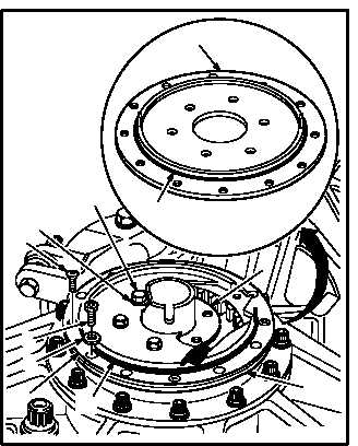
6.92.6. Installation
a. Install cover (1) on support (4). Torque six bolts
(5) to 20 INCH-POUNDS.
(1) Lubricate new packings (7) and (8). Use
petrolatum (item 138, App F).
(2) Install packings (7) and (8) on cover (1).
(3) Position cover (1) on support (4).
(4) Install six bolts (5) and washers (6).
(5) Torque six bolts (5) to 20 INCH-POUNDS.
Use torque wrench.
b. Install cover (1) on plate (2). Toque four screws
(3) to 20 INCH-POUNDS.
(1) Position cover (1) on plate (2) so that flat
section of plate (2) is midway between any
two countersunk holes in cover (1).
(2) Install three NAS1096-3-20 screws (9) and
NAS1515H3H washers (10), equally spaced
in any three non-countersunk holes in cover
(1).
(3) Slowly tighten screws (9) evenly while rotat-
ing main rotor drive shaft back and forth until
splines line up and engage.
(4) Continue to tighten screws (9) evenly until
cover (1) and plate (2) are clamped together.
(5) Install four screws (3) in countersunk holes in
cover (1).
(6) Torque four screws (3) to 20 INCH-POUNDS.
Use torque wrench.
(7) Remove three NAS1096-3-20 screws (9) and
NAS1515H3H washers (10).
GO TO NEXT PAGE
VIEW ROTATED 180º
5
3
1
2
1
M04-0512-3
9
10
6
8
4
7