TM 1-1520-238-23
6-537
6.130.
INTERMEDIATE GEARBOX TEMPERATURE SENSOR REMOVAL/INSTALLATION
6.130.1. Description
This task covers:
Removal. Cleaning. Inspection. Installation.
6.130.2. Initial Setup
Tools:
Aircraft maintenance tool kit (item 372, App H)
Light duty laboratory apron (item 27, App H)
5/8 x 3/8-inch drive open end socket wrench crowfoot
attachment (item 98, App H)
Industrial faceshield (item 129, App H)
Chemical protective gloves (item 154, App H)
10 - 50 inch-pound 1/4-inch drive click type torque
wrench (item 434, App H)
Materials/Parts:
Packing
Packing with retainer
Assembly fluid (item 30, App F)
Personnel Required:
68D
Aircraft Powertrain Repairer/NDI
67R3F
Attack Helicopter Repairer/Technical
Inspector
References:
TM 1-1520-238-T
TM 55-1500-323-24
Equipment Conditions:
Ref
Condition
1.57
Helicopter safed
2.2
Access fairings L510 and/or R510 removed
6.131
Intermediate gearbox removed (if bottom
temperature sensor to be removed)
WARNING
FLIGHT SAFETY PART
The intermediate gearbox is a flight
safety
part.
Failure
to
follow
maintenance instructions may result
in serious injury or death of
crewmembers and/or serious damage
to the helicopter.
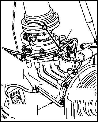
NOTE
This task is typical for all four inter-
mediate gearbox temperature sen-
sors.
Identify each sensor and each boss if
more than one sensor is removed at a
time.
GO TO NEXT PAGE
TOP AFT
TEMPERATURE
SENSOR
RIGHT SIDE
TEMPERATURE
SENSOR
BOTTOM
TEMPERATURE
SENSOR
M04-551-1
TOP FORWARD
TEMPERATURE
SENSOR