TM 1-1520-238-23
Change 8
7-109
7.32.
DIRECTIONAL SERVOCYLINDER REMOVAL – continued
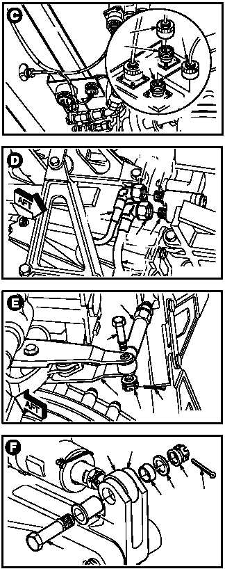
g. Detach connector (L36)P223 (15) from recep-
tacle J223 (16).
(1) Remove lockwire and anti-chafe tubing from
connector P223 (15).
(2) Remove connector (L36) P223 (15).
h. Detach connector (L36)P215 (17) from recep-
tacle J215 (18).
(1) Remove lockwire and anti-chafe tubing from
connector P215 (17).
(2) Remove connector (L36) P215 (17).
i. Remove utility pressure hose (19) from adapt-
er (20).
(1) Remove nut (21).
j. Remove utility return hose (22) from adapter
(23).
(1) Remove nut (24).
k. Remove link (25) from control arm (26).
(1) Remove and discard cotter pin (27).
(2) Hold bolt (28). Remove nut (29).
(3) Remove bolt (28).
l. Remove piston rod end (30) from bellcrank
(31).
(1) Remove and discard cotter pin (32).
(2) Hold bolt (33). Remove nut (34).
(3) Remove washer (36), bushing (37), bolt (33),
and pin (35).
GO TO NEXT PAGE
M04-779-9
15
17
16
18
ROTATED VIEW
M04-779-8
19
22
24
23
20
21
M04-779-5
25
28
26
29
27
M04-779-6
30
31
3736
34
32
35
33


