TM 1-1520-238-23
7-114
Change 8
7.33.
DIRECTIONAL SERVOCYLINDER INSTALLATION – continued
7.33.3. Installation
NOTE
Perform step a if installing a replacement
servocylinder. Go to step b if reinstalling
servocylinder.
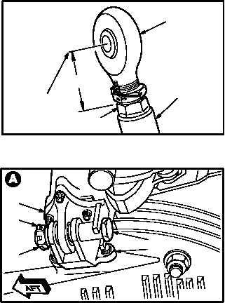
a. Measure and record distance A between cen-
ter of rod end bore (1) and top of servocylind-
er piston rod (2) on new servocylinder (3).
Ensure that distance A on new servocylinder is
within 0.016 INCH of the measurement recorded
in paragraph 7.32 on the old servocylinder. If dis-
tance A is not within 0.016 INCH, adjust rod end
(4) (para 7.34).
b. Install servocylinder (3) on bracket (5).
(1) Position servocylinder (3) on bracket (5).
(2) Install bolt (6) through bracket (5) and servo-
cylinder (3).
(3) Check fit of self-retaining bolt (6) (para 11.1).
(4) Install nut (7).
c. Torque nut (7) 450 to 570 INCH-POUNDS.
(1) Hold bolt (6). Torque nut (7) to 450 INCH-
POUNDS. Use torque wrench.
(2) Increase torque to aline cotter pin hole, but do
not exceed 570 INCH-POUNDS.
(3) Install new cotter pin (8).
GO TO NEXT PAGE
A
M04-780-19
2
1
4
3
3
8
7
6
5
M04-780-2