TM 1-1520-238-23
8-8
8.2.
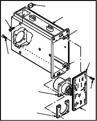
TYPICAL ENGINE INSTRUMENT INDICATOR DISASSEMBLY/ASSEMBLY (AVIM) – continued
g. Remove motherboard wiring subassembly
(14).
(1) Remove four screws (15) that hold connector
(16) and plate (17).
(2) Remove four screws (18) that hold mother-
board (19) and subassembly (14) to four
mounting blocks (20).
(3) Slide subassembly (14) and motherboard
(19) out through front of indicator case (9).
h. Remove four blocks (20).
(1) Remove four screws (21).
(2) Remove four blocks (20).
8.2.4. Cleaning
a. Wipe front panel, front panel mounting area,
circuit cards, and circuit card guide. Use cloth
(item 52, App F).
8.2.5. Inspection
a. Check engine indicator for cracks (para 8.1).
b. Inspect engine indictor for nicks and dents
(para 8.1).
c. Check indicator case for stripped or damaged
threads (para 8.1).
GO TO NEXT PAGE
21
20
15
20
20
14
19
18
17
M04-3084-9
16
9