TM 1-1520-238-23
8-10
8.2.
TYPICAL ENGINE INSTRUMENT INDICATOR DISASSEMBLY/ASSEMBLY (AVIM) – continued
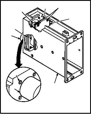
b. Install subassembly (14). Torque four screws
(18) and four screws (15) to 37 INCH-OUNCES.
(1) Place nutplate (17) over wiring near connec-
tor (16).
(2) Slide subassembly (14) and motherboard
(19) into case (9). Position against four blocks
(20).
(3) Aline connector (16) and nutplate (17) with
screw holes in case (9).
(4) Coat threads of four screws (15) and (18).
Use coating compound (item 59, App F).
(5) Install four screws (15).
(6) Torque four screws (15) to 37 INCH-
OUNCES. Use torque wrench and
screwdriver bit.
(7) Install four screws (18) to secure subassem-
bly (14) and motherboard (19) to four blocks
(20).
(8) Torque four screws (18) to 37 INCH-
OUNCES. Use torque wrench and
screwdriver bit.
c. Inspect (QA).
GO TO NEXT PAGE
20
M04-3084-11
19
16
17
14
9
18
16
15


