TM 1-1520-238-23
9-181
9.52.
PILOT INSTRUMENT PANEL MATRIX VARIABLE RESISTOR REPLACEMENT – continued
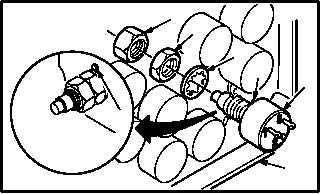
b. Install resistor (2) in panel (3).
(1) Install resistor (2) so that tab (7) seats in loca-
tor hole (8).
(2) Install lockwasher (6), nut (5), and locknut (4).
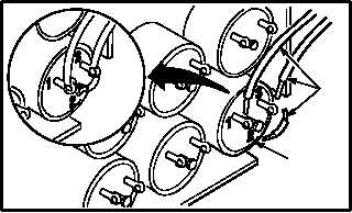
c. Apply insulation compound around base of
resistor (2). Use insulating compound kit
(item 97, App F) and brush (item 34, App F).
WARNING
Soldering iron can cause severe
burns to personnel and start fires.
Observe all safety precautions when
using soldering iron. If injury occurs,
seek medical aid.
d. Solder wires (1) to resistor (2).
(1) Solder three identified wires (1). Use
soldering iron and solder (item 189, App F)
(TM 55-1500-323-24).
e. Inspect (QA).
f. Install pilot instrument panel matrix assembly
(para 9.51).
END OF TASK
3
M04-3685-4
4
5
6
2
7
VIEW
ROTATED
8
M04-3685-5
1
2