TM 1-1520-238-23
Change 3
11-253
11.53.
CYCLIC STICK SYMBOL SELECT SWITCH REPLACEMENT – continued
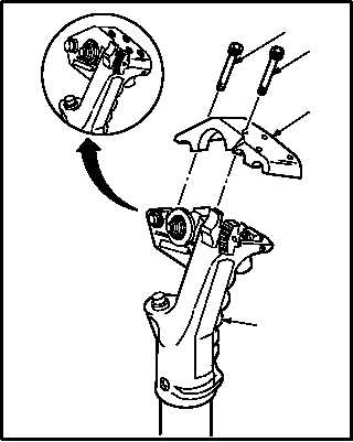
d. Install cap (1).
(1) Install cap (1) on grip (5).
(2) Install five screws (2) and screw (3).
(3) Apply a light coat of sealing compound over
heads of screws (2) and (3). Use adhesive
(item 14, App F).
e. Clean excess sealant from grip (5) (para 1.47).
f. Inspect (QA).
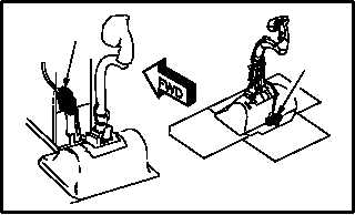
g. Detach connector P113 (8) (pilot) or P118 (9)
(CPG) as required.
(1) Check for continuity between pilot connector
P113 pins B5 and B9; pins B8 and B19 or
CPG connector P118 pins 21 and 26; pins 22
and 23, with symbol select switch in center
position. Use multimeter.
(2) Check for continuity between pilot connector
P113 pins B5 and B9; pins B7 and B8 or CPG
connector P118 pins 21 and 25; pins 22 and
23, with symbol select switch in CT position.
Use multimeter.
(3) Check for continuity between pilot connector
P113 pins B5 and B6; pins B8 and B19 or
CPG connector P118 pins 21 and 26; pins 22
and 24, with symbol select switch in HB posi-
tion. Use multimeter.
h. Attach connector P113 (8) (pilot) or P118 (9)
(CPG) as required.
i. Inspect (QA).
j. Perform symbol generator maintenance op-
erational check (TM 11-1520-238-23-2).
END OF TASK
M04-3558-5
3
2
1
5
M04-3558-6
8
9
PILOT
CPG