TM 1-1520-238-23
11-477
11.108. LATERAL F.S. 164.95 PUSH-PULL ROD ASSEMBLY REMOVAL/INSTALLATION – continued
11.108.3. Removal
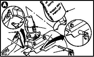
a. Enter pilot station (para 1.56). Observe all
safety precautions.
b. Secure pilot cyclic stick (1) in ZERO LONG
position and ZERO LAT position.
(1) Slowly move stick (1) to aline longitudinal rig
pin hole (2) on housing (3).
(2) Install -5 rig pin (4).
(3) Slowly move stick (1) to aline lateral rig pin
hole (5) on housing (3).
(4) Install -9 rig pin (6).
c. Install cover (7) on stick (1).
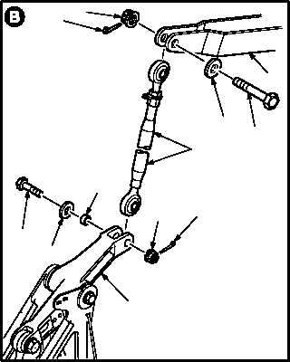
d. Remove external hydraulic power (para 1.72).
e. Remove push-pull rod assembly (8) from lat-
eral bellcrank (9).
(1) Remove and discard cotter pin (10).
(2) Remove nut (11).
(3) Remove bolt (12), washer (13), and bushing
(14).
f. Remove rod (8) from servocylinder clevis (15).
(1) Remove and discard cotter pin (16).
(2) Remove nut (17).
(3) Remove bolt (18) and washer (19) from clevis
(15).
(4) Remove rod (8).
GO TO NEXT PAGE
1
2
3
4
5
6
7
M04-4378-2
M04-4378-3
8
10
11
12
13
14
16
17
18
19
15
9