TM 1-1520-238-23
11-479
11.108.
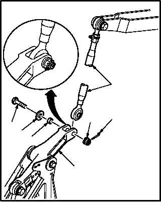
LATERAL F.S. 164.95 PUSH-PULL ROD ASSEMBLY REMOVAL/INSTALLATION – continued
b. Install rod (8) on bellcrank (9). Torque nut (11)
30 to 40 INCH-POUNDS.
(1) Aline rod (8) with bellcrank (9).
(2) Install bolt (12) through washer (13), bushing
(14), bellcrank (9), and rod (8).
(3) Check fit of self-retaining bolt (12) (para
11.1).
(4) Install nut (11).
(5) Torque nut (11) to 30 INCH-POUNDS. Use
torque wrench.
(6) Increase torque to aline cotter pin hole, but do
not exceed 40 INCH-POUNDS.
(7) Install new cotter pin (10).
c. Inspect (QA).
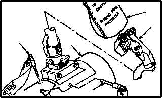
d. Remove -5 rig pin (4) and -9 rig pin (6) from
housing (3).
e. Remove cover (7) from stick (1).
f. Perform lateral flight control rigging mainte-
nance operational check (TM 1-1520-238-T).
g. Install access panel L200 (para 2.2).
END OF TASK
M04-4378-5
8
12
13
14
10
11
9
M04-4378-6
1
3
4
6
7