TM 1-1520-238-23
11-539
11.123. LONGITUDINAL F.S. 129.25 BELLCRANK BRACKET ASSEMBLY
REMOVAL/INSTALLATION – continued
11.123.6. Installation
CAUTION
To prevent damage to flight control sys-
tem components, do not use force to
aline bellcrank with bracket or to aline
push-pull rod with bellcrank.
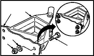
a. Install bracket (8) on airframe (16).
(1) Aline four holes in bracket (8) with holes in
airframe (16).
(2) Install four bolts (17) through bracket (8) and
airframe (16).
(3) With one person holding bolts (17), install
four washers (19) and nuts (18).
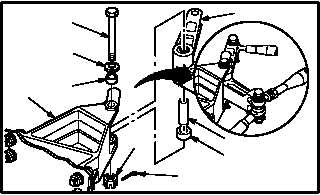
b. Install bellcrank (2) on bracket (8). Torque nut
(10) 30 to 40 INCH-POUNDS.
(1) Install bushing (15) and bearing (14) on bell-
crank (2).
(2) Aline bellcrank (2) with bracket (8).
(3) Install bolt (11) through washer (12), bushing
(13), bracket (8), and bellcrank (2).
(4) Check fit of self-retaining bolt (11) (para 11.1).
(5) Install nut (10). Torque nut (10) to 30 INCH-
POUNDS. Use torque wrench.
(6) Increase torque to aline cotter pin hole, but do
not exceed 40 INCH-POUNDS.
(7) Install new cotter pin (9).
GO TO NEXT PAGE
M04-4409-6
17
8
16
19
18
9
10
14
15
M04-4409-7
11
12
13
2
8