TM 1-1520-238-23
11-605
11.136. COLLECTIVE F.S. 161.54 PUSH-PULL ROD ASSEMBLY REMOVAL/INSTALLATION – continued
11.136.6. Installation
CAUTION
To prevent damage to flight control sys-
tem components, do not use force to
aline bellcrank with bracket or to aline
push-pull rod with bellcrank.
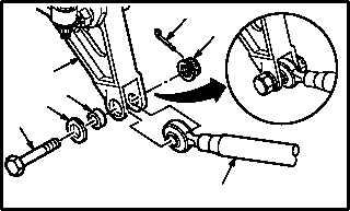
a. Install rod (13) on bellcrank (24). Torque nut
(26) 30 to 40 INCH-POUNDS.
(1) Aline rod (13) with bellcrank (24).
(2) Install bolt (27) through washer (28), bushing
(29), bellcrank (24), and rod (13).
(3) Check fit of self-retaining bolt (27) (para
11.1).
(4) Install nut (26). Torque nut (26) to 30 INCH-
POUNDS. Use torque wrench.
(5) Increase torque to aline cotter pin hole, but do
not exceed 40 INCH-POUNDS.
(6) Install new cotter pin (25).
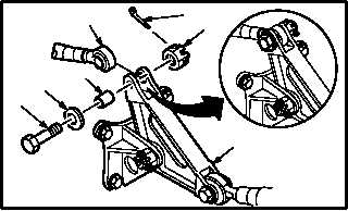
b. Install rod (13) on bellcrank (14). Torque nut
(16) 30 to 40 INCH-POUNDS.
(1) Aline rod (13) with bellcrank (14).
(2) Install bolt (17) through washer (18), bushing
(19), bellcrank (14), and rod (13).
(3) Check fit of self-retaining bolt (17) (para
11.1).
(4) Install nut (16). Torque nut (16) to 30 INCH-
POUNDS. Use torque wrench.
(5) Increase torque to aline cotter pin hole, but do
not exceed 40 INCH-POUNDS.
(6) Install new cotter pin (15).
c. Inspect (QA).
GO TO NEXT PAGE
29
28
27
13
26
25
M04-5090-7
24
14
17
16
18
19
15
M04-5090-9
13