TM 1-1520-238-23
11-865
11.197.
CPG DIRECTIONAL CONTROL POSITION LINEAR VARIABLE DIFFERENTIAL TRANSDUCER
(LVDT) INSTALLATION – continued
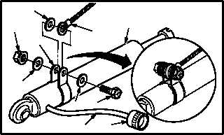
a. Install clamp (1) on LVDT (2).
(1) Position clamp (1) on LVDT (2).
(2) Install bolt (3) through washer (4), one ear of
clamp (1), electrical lead (5), washer (6), and
other ear of clamp (1).
(3) Install washer (4) and nut (7).
(4) Apply sealing compound to clamp (1), bolt
(3), washers (4), lead (5), washer (6), and nut
(7). Use sealing compound (item 175,
App F).
b. Install connector (8) on LVDT wire harness (9),
if required.
(1) Cut wire harness (9) length to 14.0 INCHES.
(2) Use Table 1 to install connector (8) on wire
harness (9) (TM 55-1500-323-24).
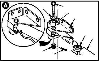
c. Install LVDT (2) on bracket (10). Torque nut (11)
14 to 18 INCH-POUNDS.
(1) Aline LVDT (2) with bracket (10).
(2) Install bolt (12) through washer (13), bushing
(14), bracket (10), and LVDT (2).
(3) Check fit of self-retaining bolt (12) (para
11.1).
(4) Install nut (11). Torque nut (11) to 14 INCH-
POUNDS. Use torque wrench.
(5) Increase torque to aline cotter pin hole, but do
not exceed 18 INCH-POUNDS.
(6) Install new cotter pin (15).
GO TO NEXT PAGE
M04-1852-6
6
5
2
7
1
4
4
3
8
9
M04-1852-8
TABLE 1
LVDT WIRE HARNESS
WHITE
BLUE
GREEN
ORANGE
CONNECTOR
PIN 1
PIN 2
PIN 3
PIN 4
12
M04-1852-2
2
10
14
11
15
13
14