TM 1-1520-238-23
11-906
11.208.
PILOT COLLECTIVE CONTROL POSITION LINEAR VARIABLE DIFFERENTIAL TRANSDUCER
(LVDT) INSTALLATION – continued
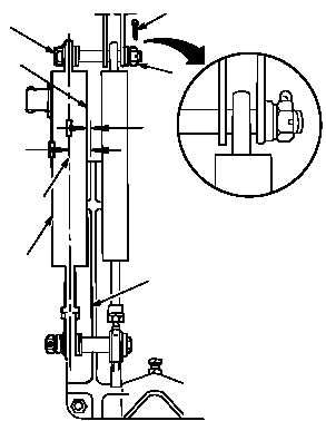
i. Check alinement of potentiometer (22). Torque
two nuts (14) 14 to 18 INCH-POUNDS.
(1) Measure distance between inboard edge of
support (23) and outboard side of potentiom-
eter (24). Distance equals 0.09 INCH.
(2) Measure distance between inboard edge of
support (23) and middle of potentiometer
(25). Distance equals 0.59 INCH.
(3) If required measurements in steps (1) and (2)
are obtained, go to step (6).
(4) If measurements in steps (1) and (2) are not
obtained, adjust washer stackups and re-per-
form step i.
(5) Check fit of self-retaining bolt (16) (para
11.1).
(6) Tighten nut (14). Torque nut (14) to 14 INCH-
POUNDS. Use torque wrench.
(7) Increase torque to aline cotter pin hole, but do
not exceed 18 INCH-POUNDS.
(8) Install new cotter pin (26).
j. Install pilot collective stick -3 rig pin (para
11.281).
k. Adjust LVDT null (para 11.216).
l. Perform pilot collective control variable resis-
tor adjustment (para 11.206).
m. Remove pilot collective stick -3 rig pin (para
11.281).
n. Inspect (QA).
o. Install pilot collective stick cover (para 11.44).
p. Perform collective flight control rigging main-
tenance operational check (TM 1-1520-238-T).
END OF TASK
M04-1746-5
16
0.59
24
26
14
0.09
23
25
22


