TM 1-1520-238-23
11-904
Change 2
11.208.
PILOT COLLECTIVE CONTROL POSITION LINEAR VARIABLE DIFFERENTIAL TRANSDUCER
(LVDT) INSTALLATION – continued
11.208.3. Installation
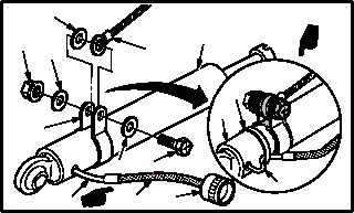
a. Install clamp (1) on LVDT (2).
(1) Position clamp (1) on LVDT (2).
(2) Install bolt (3) through washer (4), one ear of
clamp (1), electrical lead (5), washer (6), and
other ear of clamp (1).
(3) Install washer (4) and nut (7).
(4) Apply sealing compound around clamp (1),
bolt (3), washers (4), lead (5), washer (6), and
nut (7). Use sealing compound (item 175,
App F).
b. Install connector (8) and braided shielding
(8.1) on LVDT wire harness (9), if required.
(1) Cut wire harness (9) length to 10.0 INCHES.
(2) Install braided shielding (8.1) to wire harness
(TM 55-1500-323-24). Start 2.0 INCHES
from LVDT (2) body.
(3) Use Table 1 to install connector (8) on wire
harness (9) (TM 55-1500-323-24).
(4) Install braided shielding (8.1) on connector
(8).
(5) Secure wire harness (9) to LVDT (2) body.
(a) Create service loop on wire harness (9).
(b) Secure wire harness (9) with strap (9.1).
Use strap (item 193, App F).
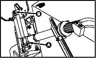
c. Enter pilot station (para 1.56). Observe all
safety precautions.
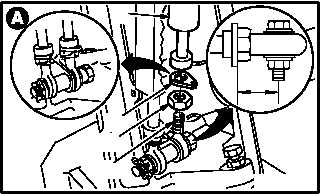
d. Install LVDT (2) on rod end (10).
(1) Install nut (11) and keywasher (12) on rod end
(10).
(2) Install LVDT (2) on rod end (10).
(3) Measure 1.0 INCH between center of rod end
(10) and keywasher (12).
(4) Tighten nut (11).
GO TO NEXT PAGE
M04-1746-6A
6
5
2
7
4
1
4
3
8
8.1
9
9.1
2
9
M04-1746-2A
PILOT STATION
LEFT SIDE
M04-1746-8
TABLE 1
LVDT WIRE HARNESS
WHITE
BLUE
GREEN
ORANGE
CONNECTOR
PIN 1
PIN 2
PIN 3
PIN 4
M04-1746-4
2
11
12
10
1.0 IN.


