TM 1-1520-238-23
11-1040
11.246.
DIRECTIONAL F.S. 199.25 BELLCRANK INSTALLATION – continued
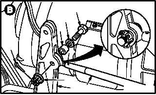
c. Install aft push-pull rod (12) on bellcrank (3).
Torque nut (13) 30 to 40 INCH-POUNDS.
(1) Aline rod (12) with bellcrank (3).
(2) Install sleeve bushing (14) in bellcrank (3).
(3) Install bolt (15) through washer (16), bushing
(14), bellcrank (3), and rod (12).
(4) Check fit of self-retaining bolt (15) (para
11.1).
(5) Install nut (13). Torque nut (13) to 30 INCH-
POUNDS. Use torque wrench.
(6) Increase torque to aline cotter pin hole, but do
not exceed 40 INCH-POUNDS.
(7) Install new cotter pin (17).
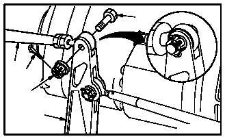
d. Install forward push-pull rod (18) on bellcrank
(3). Torque self-locking nut (19) 30 to 40 INCH-
POUNDS.
(1) Aline rod (18) with bellcrank (3).
(2) Install close tolerance bolt (20) through bell-
crank (3) and rod (18).
(3) Check fit of self-retaining bolt (21) (para
11.1).
(4) Install nut (19). Torque nut (19) to 30 INCH-
POUNDS. Use torque wrench.
(5) Increase torque to aline cotter pin hole, but do
not exceed 40 INCH-POUNDS.
(6) Install new cotter pin (21).
e. Inspect (QA).
f. Perform directional flight control rigging
maintenance
operational
check
(TM 1-1520-238-T).
g. Install access panel L200 (para 2.2).
END OF TASK
13
3
16
14
15
12
17
M04-1787-5
20
18
21
19
3
M04-1787-6