TM 1-1520-238-23
11-1170.2
Change 7
11.276A. TAIL ROTOR ELECTRICAL BRUSH AND BRUSH HOLDER REMOVAL/INSTALLATION – continued
11.276A.3. Removal
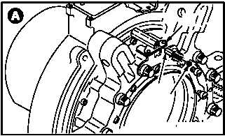
a. Remove electrical brush (1) from brush hold-
er (2).
(1) Remove set screw (3) from brush holder (2).
(2) Remove electrical brush (1) from brush hold-
er (2). Discard electrical brush (1).
11.276A.4. Cleaning
a. Clean removed and attaching parts (para
1.47).
11.276A.5. Inspection
a. Check set screw for damaged threads and
worn key flats. None allowed.
b. Check removed and attaching parts for dam-
age (para 11.232).
c. Check removed and attaching parts for corro-
sion (para 1.49).
11.276A.6. Installation
NOTE
For proper preparation of bonding sur-
face on pitch horn for brush holder, refer
to TM 55-1500-323-24.
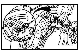
a. Install electrical brush (1) in brush holder (2).
(1) Insert new brush (1) into brush holder (2).
(2) Install set screw (3) into brush holder (2).
Turn set screw four 360 turns.
b. Inspect (QA).
c. Install tail rotor electrical lead (para 11.276).
d. Install access fairing L540 (para 2.2).
END OF TASK
3
1
M04-5230-2
2
3
1
M04-5230-3
2


