TM 1-1520-238-23
12-104
12.34.
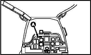
PILOT ENGINE FIRE PULL SWITCH REMOVAL/INSTALLATION
12.34.1. Description
This task covers:
Removal. Cleaning. Inspection. Installation.
12.34.2. Initial Setup
Tools:
Electrical tool kit (item 378, App H)
Light duty laboratory apron (item 27, App H)
Chemical protective gloves (item 154, App H)
Electric gun type heater (item 163, App H)
Adjustable air filtering respirator (item 262, App H)
Soldering gun (item 334, App H)
Materials/Parts:
Splice (2)
Insulation sleeving (item 105, App F)
Solder (item 189, App F)
Personnel Required:
68X
Armament/Electrical System Repairer
One person to assist
68X3F
Armament/Electrical System Repairer/
Technical Inspector
References:
TM 1-1520-238-T
TM 55-1500-323-24
Equipment Conditions:
Ref
Condition
1.57
Helicopter safed
2.179
Nontransparent barrier removed
NOTE
This task is typical for No. 1 or No. 2 pilot
engine fire pull switch.
12.34.3. Removal
a. Enter pilot station (para 1.56). Observe all
safety precautions.
b. On pilot center circuit breaker panel, open
FIRE EXTGH PLT, CPG, and APU circuit break-
ers.
GO TO NEXT PAGE
PILOT STATION
M04-984-1