TM 1-1520-238-23
12-128
Change 3
12.40.
FIRE EXTINGUISHER CARTRIDGE REMOVAL/INSTALLATION
12.40.1. Description
This task covers:
Removal. Cleaning. Inspection. Installation.
12.40.2. Initial Setup
Tools:
Aircraft mechanic’s tool kit (item 376, App H)
Light duty laboratory apron (item 27, App H)
15/16 x 3/8-inch drive open end box socket wrench
crowfoot attachment (item 80, App H)
Industrial faceshield (item 129, App H)
Chemical protective gloves (item 154, App H)
1 1/16 & 1 1/4-inch open end wrench (item 416, App H)
30 - 150 inch-pound 3/8-inch drive click type torque
wrench (item 441, App H)
Materials/Parts:
Packing
Petrolatum (item 138, App F)
Wire (item 226, App F)
Personnel Required:
67R
Attack Helicopter Repairer
67R3F
Attack Helicopter Repairer/Technical
Inspector
Equipment Conditions:
Ref
Condition
1.57
Helicopter safed
12.38
Primary and/or reserve fire extinguisher re-
moved
NOTE
This task is typical for engine No. 1, en-
gine No. 2, and APU fire extinguisher car-
tridges.
WARNING
Each actuator stud must be wired to
ground stud to prevent accidental
explosion of cartridge. All person-
nel must wear safety goggles when
removing and installing cartridges.
Accidental explosion could cause
injury to personnel. If injury occurs,
seek medical aid.
Do not loosen sensor housing or
container. Container could dis-
charge and injure personnel. If inju-
ry occurs, seek medical aid.
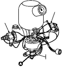
GO TO NEXT PAGE
ENGINE
NO. 1
CARTRIDGE
ENGINE
NO. 2
CARTRIDGE
APU
CARTRIDGE
M04-997-1