TM 1-1520-238-23
Change 7
12-135
12.42.
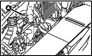
FIRE EXTINGUISHER STOP CHECK VALVE REPLACEMENT
12.42.1. Description
This task covers:
Removal. Cleaning. Inspection. Installation.
12.42.2. Initial Setup
Tools:
Aircraft mechanic’s tool kit (item 376, App H)
1 1/16 & 1 1/4-inch open end wrench (item 416, App H)
1 & 1 1/8-inch open end wrench (item 417, App H)
Light duty laboratory apron (item 27, App H)
Chemical protective gloves (item 154, App H)
Industrial goggles (item 156, App H)
Adjustable air filtering respirator (item 262, App H)
Materials/Parts:
Brush (item 36, App F)
Cloth (item 52, App F)
Corrosion preventive compound (item 63A, App F)
Corrosion removing compound (item 64B, App F)
Personnel Required:
67R
Attack Helicopter Repairer
67R3F
Attack Helicopter Repairer/Technical
Inspector
References:
TM 1-1520-238-T
Equipment Conditions:
Ref
Condition
1.57
Helicopter safed
2.2
Access doors T250L, T250R, T290L,
T290R, and L325 opened
13.17
Air duct No. 1 removed (if required)
NOTE
This task is typical for No. 1 engine, No. 2
engine, or APU fire extinguishing stop
check valves.
12.42.3. Removal
a. Enter pilot station (para 1.56). Observe all
safety precautions.
b. On pilot center circuit breaker panel, open
FIRE EXTGH PLT, CPG, and APU circuit break-
ers.
GO TO NEXT PAGE
M04-993-1