TM 1-1520-238-23
12-174
12.56.
BLADE DE-ICE CONTROLLER ADJUSTMENT - continued
12.56.3. Main Rotor Resistance Measurement
a. Enter pilot station (para 1.56). Observe all
safety precautions.
b. On pilot aft circuit breaker panel, open ECS
ICE DET, BLADE DE-ICE, and BLADE DE-ICE
CONTR circuit breakers.
c. Measure air and main rotor blade (1) tempera-
ture.
(1) Measure and record air temperature in de-
grees Celsius. Use multimeter and probe.
(2) Measure and record rotor blade (1) surface
temperature at upper leading edge (2) of
blade root. Use multimeter and probe. Press
probe on root fitting and wait until reading
stabilizes.
(3) Repeat steps c.(1) and c.(2) if difference be-
tween blade (1) temperature and air tempera-
ture is greater than 2 C.
(4) Record blade (1) temperature if value deter-
mined in step c.(3) is less than 2 C. Use
nearest whole number.
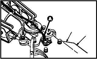
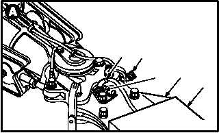
d. Install calibration test adapter (3) on rotor
blade (1).
(1) Record rotor blade (1) serial number and de-
ice power connector (4) number.
(2) Remove lockwire between de-ice power con-
nector (4) and blade heater element recep-
tacle J1 (5).
(3) Detach de-ice power connector (4) from
blade heater element receptacle J1 (5).
(4) Attach calibration test adapter (3) connector
P1 (6) to blade heater element receptacle J1
(5).
GO TO NEXT PAGE
2
1
M04-3159-1
3
5
4
6
M04-3159-4
1