TM 1-1520-238-23
12-179
12.56.
BLADE DE-ICE CONTROLLER ADJUSTMENT - continued
12.56.6. Calibration Module Adjustment
NOTE
The following relationship exists between
calibration modules and main and tail ro-
tor blades:
Calibration
Module
Rotor
Blade
P10
Tail Rotor Blade
P11
Main Rotor P1
P12
Main Rotor P2
P13
Main Rotor P3
P14
Main Rotor P4
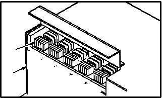
a. Remove calibration module (17) to be ad-
justed from de-ice controller (13).
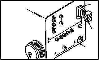
b. Install module (17) in calibration test adapter
(3) receptacle J2 (18).
NOTE
Each main rotor blade calibration module contains five variable resistors which must be set to
resistances determined, using Table I. Tail rotor blade calibration module contains a single variable
resistor which is set, using Table II. Calibration module adjustment is typical except for number of
resistors.
The following relationships exist between main rotor heater element test points, calibration module
variable resistors, and module resistor test points:
Heater Element
Test Points
Variable Resistors
Module Resistor
Test Points
TP1 - TP5
R1
TP - R1
TP2 - TP5
R2
TP - R2
TP3 - TP5
R3
TP - R3
TP4 - TP5
R4
TP - R4
TP6 - TP5
R5
TP - R5
GO TO NEXT PAGE
17
13
P10
P11
P12
P13
P14
M04-3159-9
M04-3159-10
18
17
3