TM 1-1520-238-23
12-176
12.56.
BLADE DE-ICE CONTROLLER ADJUSTMENT - continued
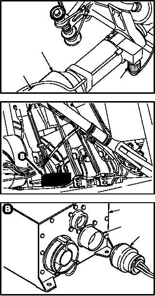
12.56.4. Tail Rotor Resistance Measurement
a. Measure air and tail rotor blade (9) tempera-
ture.
(1) Verify tail rotor heating connectors P999,
P1034, P1035, and P1036 (8) are attached
and lockwired to corresponding tail rotor
blades (9).
(2) Measure and record air temperature in de-
grees Celsius. Use multimeter and probe.
(3) Measure and record temperature of tail rotor
blade (9) at root fitting (10). Use multimeter
and probe. Press probe on root fitting (10)
and wait until reading stabilizes.
(4) Repeat steps a.(2) and a.(3) if difference be-
tween blade (9) temperature and air tempera-
ture is greater than 2 C.
(5) Record blade (9) temperature if value deter-
mined in step a.(4) is less than 2 C. Use
nearest whole number.
b. Detach connector P791 (11) from receptacle
(A311)J1 (12) on de-ice controller (13).
c. Attach connector P791 (11) to calibration test
adapter (3) receptacle J1 (14).
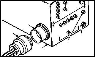
d. Perform tail blade heater element resistance
measurements.
(1) Measure and record resistance for tail rotor
heater elements between test points TP-G
(15) and TP-F (16) on calibration test adapter
(3). Measure value to nearest 10 milliohms.
Use ohmmeter.
e. Detach connector P791 (11) from calibration
test adapter (3) receptacle J1 (14).
f. Attach connector P791 (11) to receptacle
(A311)J1 (12) on de-ice controller (13).
GO TO NEXT PAGE
M04-3159-5
10
8
9
M04-3159-6
M04-3159-7
13
12
11
11
14
3
15
16
M04-3159-8