TM 1-1520-238-23
12-180
Change 2
12.56.
BLADE DE-ICE CONTROLLER ADJUSTMENT - continued
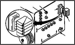
c. Adjust calibration module (17).
(1) Remove and retain adhesive tape covering
five variable resistors (19) on module (17).
(2) Measure resistance between appropriate
module resistor test point (20) and common
test point (21) on calibration test adapter (3).
Use ohmmeter.
(3) Adjust resistors (19) on module (17) to resist-
ances determined, using Table I or II. Adjust-
ment accuracy of 10 OHMS is acceptable.
(4) Replace adhesive tape over resistors (19) on
module (17).
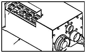
d. Install module (17) in de-ice controller (13).
(1) Remove module (17) from calibration test
adapter (3) receptacle J2 (18).
(2) Install module (17) in de-ice controller (13).
e. Repeat steps a. thru d. for all calibration mod-
ules (17).
f. Inspect (QA).
g. Perform rotor blades de-ice maintenance op-
erational check (TM 1-1520-238-T).
h. Install access panel R200 (para 2.2).
GO TO NEXT PAGE
M04-3159-1 1
17
3
20
21
19
18
13
M04-3159-12
17