TM 1-1520-238-T-4
Change 9
5–47
5–21.
FLIGHT CHECK AND ADJUSTMENT USING AVA EQUIPMENT (cont)
5–21
(12) If measured values exceed specifications, press DO to execute diagnostics. AVA will make
recommendations to correct excessive vibration. Review ‘‘WHAT YOU SHOULD KNOW BEFORE ENTERING
DIAGNOSTICS” and Step c., ‘‘INTERPRETING RESULTS AND MAKING CORRECTIONS.”
(13) After corrections are made, refly aircraft and repeat step b. to recheck the 1/REV vibrations through
required flight conditions.
NOTE
If a weight adjustment is required, go to paragraph 5–20, step e.
If a pitch link adjustment is required, go to paragraph 5–19, step c.
If a trim tab adjustment is required, go to step d.
(14) Remove Aviation Vibration Analysis equipment (TM 1-1520-238-23).
(15) Inspect (QA).
WHAT YOU SHOULD KNOW BEFORE ENTERING DIAGNOSTICS
Before entering diagnostics it may be beneficial to view the in flight vertical readings on the polar plot and the in
flight track trend. By doing this before entering diagnostics, it will give a good indication of what will be required to
smooth the aircraft.
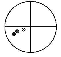
Figure 5–18 illustrates a polar plot display of the in flight vertical vibration readings from the AVA:
1.40
AH64
333
FLOWN
11:58:00 28 AUG 96
ID TEST
AMP
[IPS]
PHASE
[DEG]
VERT
1R VER
A FPG100
0.11
0.12
332.65
109.39
B Hover
M58-0295-3
G
F
C
C 60K
D 80K
E 100K
F 120K
G 140K
0.33
0.57
0.55
0.55
1.02
242.17
251.20
249.86
252.82
248.75
Figure 5–18.
Polar Plot Display
By viewing the display above and the AH-64 coefficient polar chart for vertical vibration at the end of this section,
this clearly shows that blade 1, blade 3, or both will require adjusting to move the vibration points towards the
center. To move the vibrations points towards center for this example would required blade 1 to be tabbed down
(or pitch linked down) or blade 3 to be tabbed up (or pitch linked up).