TM 1-1520-238-T-4
5–56
Change 9
5–21.
FLIGHT CHECK AND ADJUSTMENT USING AVA EQUIPMENT (cont)
5–21
as easy to determine which move caused this overreaction. The recommended procedure in this case is let the
AVA tell you what moves are required to bring the vibration back, by utilizing the custom solution options that were
described earlier in step c.(2).
Remember–if the vibration trend shows that the levels are moving toward the center of the polar chart, then
everything is working properly. When the level moves towards the center, the only thing to obtain is whether the
move was too much, not enough or just right. If the vibration does not move towards center, something was done
wrong. If multiple moves were made it is very difficult to determine which move was done improperly (most likely
to the wrong blade or in the wrong direction). If the vibration trend shows vibration levels moving in a direction
other than towards center, you should stop and try to figure what was done wrong. If it cannot be determined what
went wrong then it is recommended to make another adjustment, according to the AVA, but try to make as few of
moves as possible (usually 1 to 2 moves) to reduce the vibration levels. See “Utilizing the MAXIMUM # OF
ADJUSTMENTS” from step c.
c. If a weight adjustment is required, follow paragraph 5–20, step e.
d. If a pitch link adjustment is required, follow paragraph 5–19 ,step c.
e. If a trim tab adjustment is required, follow step d.
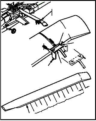
d. TRIM TAB ADJUSTMENTS
1. Tab bend corrections called out on the
diagnostics display will refer to the start point of
a continuous bend. Example: If AVA
recommends 1 degree up at pocket #4–10, bend
should start at pocket #4 and continue through
pocket #10.
(a). Place tab adjustment tool in center of tab
bend pocket which is to be bent.
(b). Tab tracking locations (#0 through 10) are 10
inches in length, starting six inches inboard
of swept tip. Do not bend inboard of pocket
#10 (2). If trim tab pockets are not marked or
improperly marked refer to
(TM 1-1520-238-23) (Main Rotor Blade Trim
Tab Markings).
(c). Do not make bends in opposite direction in
adjacent pockets. It is preferable to remove
an upward bend (reset to Zero degrees) if
adjacent pocket requires a downward bend.
(d). Any noticeable deformity (kinks or sharp
edges caused by tab bending tool) is cause
for rejection of blade.
(e). It is preferable to make two 1–degree bends
in adjacent stations rather than one
2–degree bend in one station.
2. Perform tab adjustments on blades and pockets called out in AVA diagnostics.
3. Remove tab adjustment tools and repeat step b.
4. Perform limited test flight, including autorotational RPM check (TM 1-1520-238-MTF).
END OF TASK
M58-0295-9
THUMB SCREW
WING NUT
TAB ADJUSTMENT TOOL
0
1
2
3
5
6
7
8
9
10
6"
4
100% NR/
HOVER
TRACK
140 V
100-140
KNOTS
60-100
KNOTS
TAB ADJUSTMENT TOOLS
(INSTALLED)
1
2
NE
TAB ANGLE GAGE
TOOL ASSEMBLY