TM 1-1520-238-T-4
6–6
6–2
LOCATION AND DESCRIPTION OF MAJOR COMPONENTS (cont)
6–2
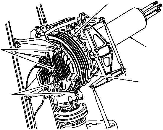
d. TGB Assembly.
The TGB assembly (fig. 6–5) transmits power from the IGB to drive the TGB. The TGB,
mounted on the vertical stabilizer, is coupled to the IGB by drive shaft 6. The tail rotor drive shaft, part of the
gearbox, is located inside the static support. Some of the tail rotor components are mounted on the static supports
which carry loads placed on the tail rotor drive shaft. The TGB assembly consists of the housing assembly, static
support, four thermistors, and an accelerometer.
(1) The housing assembly supports the TGB components. The housing assembly includes a breather vent
which prevents the TGB from being overpressurized. The vent is filled with curled steel mesh to provide a filter
element.
(2) The static support, mounted to the output cover assembly and collar, supports the tail rotor swash plate
assembly and the tail rotor assembly. The static support transmits all flight loads from the TGB to the housing
assembly.
(3) The tail rotor drive shaft assembly has three studs to connect it to the tail rotor fork assembly.
(4) Four thermistors, installed to monitor the temperature of the duplex and roller bearings, are
spring–loaded to maintain constant contact with the bearing housing.
(5) An accelerometer, installed on the lower end of the housing assembly, monitors vibrations inside the
TGB. Excessive vibration causes the VIB GRBX indicator to light on the pilot’s caution/warning panel.
M58-285
THERMISTORS
THERMISTORS
HOUSING ASSEMBLY
ACCELEROMETER
SUPPORT
STATIC
Figure 6–5.
TGB Assembly