TM 1-1520-238-T-4
6–2
SECTION I.
EQUIPMENT DESCRIPTION AND DATA
6–1.
EQUIPMENT CHARACTERISTICS, CAPABILITIES, AND FEATURES
6–1
a. Characteristics.
The drive system changes the angle of drive and converts the output rpm of the
engines into usable power to drive the main rotor system, tail rotor system and the gear driven accessories.
b. Capabilities.
The drive system uses power from the auxiliary power unit (APU) to drive aircraft
accessories when the engines are not operating and can be operated with either engine.
c. Features.
Operating conditions of the transmission and engine nose gearboxes (NGBs) are monitored
by the fault detection and location system (FD/LS) via the multiplex subsystem.
6–2.
LOCATION AND DESCRIPTION OF MAJOR COMPONENTS
6–2
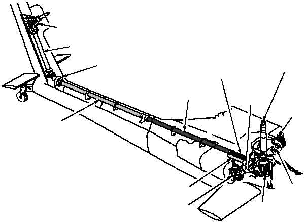
Drive System.
The drive system (fig. 6–1) consists of the engine NGB assemblies 1 and 2, the main
transmission assembly, the intermediate gearbox (IGB) assembly, the tail rotor gearbox (TGB) assembly, and the
drive shaft assembly (7 drive shafts).
TGB ASSEMBLY
DRIVE SHAFT 6
INPUT
DRIVE
SHAFT 2
ENGINE NGB
ASSEMBLY 1
DRIVE SHAFT 5
DRIVE SHAFT 4
APU DRIVE SHAFT 7
DRIVE SHAFT 3
INPUT
DRIVE SHAFT 1
MAIN
TRANSMISSION
ASSEMBLY
M58-182A
IGB ASSEMBLY
ENGINE NGB
ASSEMBLY 2
STATIC MAST
(MAIN ROTOR DRIVE SHAFT
INSIDE)
Figure 6–1.
Drive System