TM 1-1520-238-T-6
9–99
9–7.
SYSTEM DESCRIPTION (cont)
9–7
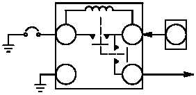
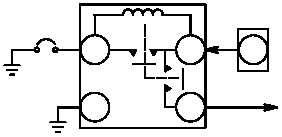
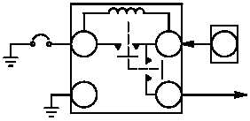
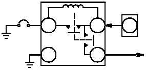
(13) CPG Station DC Ground Circuit Protection System.
The CPG station dc ground circuit protection
system (fig. 9–92) saves weight by eliminating large portions of heavy wiring, reduces cost, maintains a constant
load voltage due to parallel circuitry, and protects the hellfire mission equipment (HME).
(a) Operation of the L OUTBD LCHR DC circuit breaker (CB25) in conjunction with a RCCB is the same
for HME circuit breakers and associated RCCBs. Only the L OUTBD LCHR DC circuit breaker (CB25) and
associated RCCB is explained.
(b) When power is applied to the missile system, current flows from ground through L OUTBD LCHR
DC circuit breaker (CB25) to the RCCB. Current flows from contact 3 of the RCCB through the coil to contact A1
energizing the RCCB. When the RCCB is energized, the dc bus is connected to the left outboard launcher dc
load. When an overload condition occurs, the current through the L OUTBD LCHR DC circuit breaker increases
(CB25), opening the L OUTBD LCHR DC circuit breaker (CB25). When the L OUTBD LCHR DC circuit breaker
(CB25) is opened, the RCCB deenergizes, removing the left outboard launcher load from the dc bus.
A1
A2
3
5A
28 VDC LOAD
DC
BUS
RCCB
MSL
L INBD
LCHR DC
CB23
CB202
A1
A2
3
5A
28 VDC LOAD
DC
BUS
MSL
L OUTBD
LCHR DC
CB25
A1
A2
3
5A
28 VDC LOAD
DC
BUS
MSL
R OUTBD
LCHR DC
CB19
A1
A2
3
5A
28 VDC LOAD
DC
BUS
MSL
R INBD
LCHR DC
CB22
A1
A2
3
5A
28 VDC LOAD
DC
BUS
RCCB
RCCB
RCCB
MSL
ARM
CB27
CB201
CB203
CB204
RCCB
CB3
M69-370
Figure 9–92.
CPG Station DC Ground Circuit Protection System Interface Diagram