TM 1-1520-238-T-7
10–44
10–7.
SYSTEM DESCRIPTION (cont)
10–7
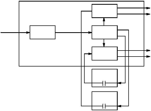
FORWARD FSC
OSCILLATOR
AFT FSC
AFT FUEL
CELL SENSOR
FORWARD FUEL
CELL SENSOR
POWER
SUPPLY
FSC
OPERATING
VOLTAGES
TO FUEL QTY
INDICATOR
TO REFUEL
INDICATOR
0-5 VDC
0-5 VDC
TO FUEL QTY
INDICATOR
TO REFUEL
INDICATOR
28/24 VDC
INPUT
M70-209
HZ
Figure 10–19.
FSC Functional Block Diagram
(k) The CPG selectable digital display (fig. 10–20) selects pilot instrument data for display on the digital
readouts. The SELECT switch selects the indicator data to be displayed. At the same time the indicator light on
the display indicates the selected indicator. The TEST switch position tests the CPG selectable digital display and
CPG engine torque instrument displays and readouts.
e. Nitrogen Inerting System.
(1) Purpose.
The purpose of the nitrogen inerting system is to provide pressurized air to the fuel cells
and reduce the amount of oxygen to a level that will not support combustion.
(2) System Operation (fig 10–21).
(a) Pressurized air from the PAS enters the NIU. The pressurized air is regulated by the NIU to 25 3
psi. The NIU delivers the regulated air, which is 94% nitrogen, through the nitrogen check valve to the fuel cells.
Cooling air is drawn into and exhausted from the NIU. The nitrogen check valve is an in-line valve that provides
1-way flow of nitrogen enriched air to the fuel cells. The fuel vent shutoff valve is a spring-loaded valve that is
closed during NIU operation to prevent nitrogen from being vented out of the fuel cells.