TM 1-1520-238-T-7
10–46
10–7.
SYSTEM DESCRIPTION (cont)
10–7
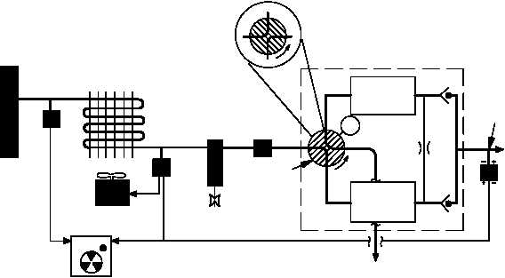
(b) The NIU (fig. 10–22) receives pressurized air from the PAS manifold. The pressure switch senses
the pressure and closes, sending a signal to the NIU monitor which activates a timing circuit. The timing circuit
provides a 10 second delay to allow the NIU to come on line before energizing the NITROGEN INERT MONITOR
indicator.
(c) Air flows through the heat exchanger where it is cooled to approximately 25 F (-3.9 C) of the
ambient air temperature. The air exiting the heat exchanger passes over a thermistor. If the temperature is below
40 F (4.4 C), the thermistor turns the fan off. If the temperature is above 140 F (60 C), the thermistor turns the
fan on. Before entering the pressure regulator, the air enters the filter/water separator and condensation is drained
overboard. The pressure regulator regulates the air pressure to 25 3 psi.
(d) Regulated air enters the air separation module and is directed to one of two sieve cannisters. The
selected sieve canister traps approximately 71% of the oxygen molecules and outputs the nitrogen-rich air
through a check valve to the pressure transducer. A portion of the nitrogen-rich air is fed back through a metering
orifice of the other cannister to flush the trapped oxygen molecules out the overboard exhaust. The pressure
transducer monitors the pressurized output. If the pressure is insufficient, the pressure transducer fails the
NITROGEN INERT MONITOR indicator. The fuel cells receive an output air mixture of 93.5% to 94.0% nitrogen
and 6.0% to 6.5% oxygen.
TO FUEL CELL
6.0-6.5% OXYGEN
93.5-94% NITROGEN
ROTARY
VALVE
PAS
MANIFOLD
(21% OXYGEN)
EXHAUST
OVERBOARD
VENT
115 VAC
M
SIEVE
CANISTER 1
AIR SEPARATION MODULE
90º ROTATION
PRESSURE
REGULATOR
FILTER/WATER
SEPARATOR
THERMISTOR
PRESS
TO TEST
FAN
115 VAC
PRESSURE
SWITCH
HEAT
EXCHANGER
PRESSURE
TRANSDUCER
NITROGEN INERT
MONITOR INDICATOR
(AFT AVIONICS BAY)
SIEVE
CANISTER 2
M70-213
Figure 10–22.
NIU Functional Block Diagram
f. Pressure Refueling/Defueling System.
(1) Purpose.
The purpose of the pressure refueling/defueling system is to provide a means pressure
refueling or suction defueling of the forward and aft fuel cells.
(2) System Operation.
(a) The refueling panel provides a means of controlling refuel operations and monitoring fuel quantity
during refueling/defueling operations.