TM 1-1520-238-T-7
11–44
11–7.
SYSTEM DESCRIPTION (cont)
11–7
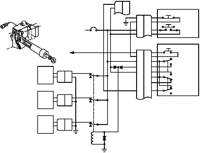
(2) System Operation (fig. 11–15). The force trim system must be operating for the DASE system to be
fully operational. When the pilot’s cyclic FORCE TRIM REL switch is OFF, power is not applied to the magnetic
brakes. The pilot and CPG are in full control of the cyclic sticks and directional pedals. When the pilot’s cyclic
FORCE TRIM REL switch is ON, force trim power of 28 VDC is applied through the TRIM circuit breaker (CB87)
to the pilot’s cyclic FORCE TRIM REL switch, the CPG’s cyclic TRIM switch, and contacts A2, B2, and C2 of the
trim brake relay. Contact A2 mates with A3, B2 mates with B3, and C2 mates with C3, providing 28 VDC to the
pitch, roll, and yaw magnetic brakes. The magnetic brakes engage and lock the cyclic sticks and directional
pedals in the position selected by the pilot. When the pilot or CPG moves the cyclic stick and directional pedals
during force trim operation the feel spring assembly is compressed. The feel spring assembly allows the force trim
to be overridden without resetting the force trim. When the cyclic stick and directional pedals are released, the feel
trim assemblies return the cyclic sticks and directional pedals to the force trim setting. When the pilot’s cyclic
FORCE TRIM REL switch or the CPG’s cyclic TRIM switch RELEASE position is depressed, a ground is supplied
to the trim brake relay. The trim brake relay energizes and removes 28 VDC from the magnetic brakes allowing
the pilot and CPG to be in full control of the cyclic sticks and directional pedals. When the switch is released, a
new force trim reference is established.
ASE PANEL
4 AND 5, 7 AND 8, 10 AND 11
FORCE TRIM RELEASE (MOMENTARY)
4 AND 5, 8 AND 9, 10 AND 11
FORCE TRIM ON (NORMAL)
5 AND 6, 8 AND 9, 11 AND 12
FORCE TRIM OFF (PERMANENT)
TRIM BRAKE
RELAY
RTN
+ 28 VDC
+ 28 VDC
ROLL
RTN
PITCH
RTN
+ 28 VDC
YAW
ASE
RELEASE
SW
CPG CYCLIC STICK
MONITORING
DASEC
5A
28 VDC
CB 87
TRIM
M70-253
X1
X2
A3
A2
B
A
K1 - 9 / 10
B3
B2
C3
C2
116
117
7
6
2
1
A1
B1
C1
TRIM
RELEASE
SW
B
A
B
A
ASE
RELEASE
SW
PILOT CYCLIC STICK
A2
A1
TRIM
RELEASE
SW
A9
11
10
12
A10
A11
A5
7
9
4
6
8
5
(SHOWN IN
NORMAL
POSITION)
Figure 11–15.
Force Trim System Functional Block Diagram


