TM 1-1520-238-T-7
11–45
11–7.
SYSTEM DESCRIPTION (cont)
11–7
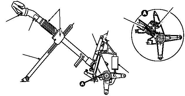
c. Collective Flight Control System.
(1) Purpose.
The purpose of the collective flight control system is to provide mechanical control input to
the main rotor system for vertical flight control of the helicopter.
(2) System Operation.
(a) The pilot and CPG collective sticks (fig. 11–16) are moved up or down to control vertical movement
of the helicopter. The grip assembly is used as a handle to control the collective stick. The friction adjust twist grip
and housing assembly locks the collective stick in a desired position. Rotation of the grip (counterclockwise)
applies pressure through the housing assembly to the friction guide, holding the collective stick in the desired
position. Rotation of the grip (clockwise) releases pressure, allowing the collective stick to move. The guarded
BUCS select trigger switch, on the collective stick, is active only in the CPG position. When the guard is raised
and the BUCS select trigger switch is depressed, BUCS control is transferred from the pilot to the CPG.
(b) The pilot main rotor engine speed droop LVDT monitors collective stick movements. An electrical
signal is developed proportional to collective stick movement and sent to the engine control units to maintain 100
percent rotor rpm. The pilot and CPG collective LVDTs monitor collective stick movements during DASEC, CAS
and BUCS operation. An electrical signal is developed proportional to collective stick movement and sent to the
collective servocylinder to position the main rotor head.
(c) A 1G spring assembly, connected to each of the collective sticks, provides a force of approximately
54 lbs. to counterbalance the weight of the collective stick.
(d) The SPAD, during normal operation, is part of the mechanical linkage. When jamming prevents
normal collective stick movement, a force of 45 foot-lbs. on either collective stick will cause the SPAD shear pin to
snap, severing the mechanical linkage and activating BUCS. When the CPG’s shear pin snaps, the BUCS select
trigger switch on the CPG’s collective stick must be closed to activate BUCS. The pilot and CPG caution/warning
panels BUCS ON indicator lights when BUCS is activated. If BUCS fails, the pilot and CPG master
caution/warning panels BUCS FAIL indicator lights.
SPAD
SHEAR PIN
M70-255
FRICTION
GUIDE
GRIP
ASSEMBLY
BUCS SELECT
TRIGGER SWITCH
AND HOUSING ASSEMBLY
FRICTION ADJUST TWIST GRIP
LVDT
SWITCH
ASSEMBLY
1G SPRING
ASSEMBLY
Figure 11–16.
Collective Stick Interface Diagram