TM 1-1520-238-T-7
11–49
11–7.
SYSTEM DESCRIPTION (cont)
11–7
(d) The mixer assembly longitudinal bellcrank receives input motion from the longitudinal servocylinder
and transmits longitudinal linear motion to the rear longitudinal bellcrank through two longitudinal links. An
increase in forward motion to the cyclic stick mechanical input causes the longitudinal servocylinder to retract.
Retraction of the longitudinal servocylinder pivots the longitudinal bellcrank downward as the two longitudinal links
move forward and pivot the rear longitudinal bellcrank upward. The mixer assembly changes the longitudinal
linear motion into vertical linear motion which is applied to the torque link. The torque link moves upward, tilting
the nonrotating swashplate forward. The nonrotating swashplate transmits the movement to the scissor
assemblies. The scissor assemblies transmit rotational power to the rotating swashplate. The rotating swashplate
transmits the movement to the pitch link assemblies changing the pitch angle on the main rotor blades.
e. Lateral (Cyclic) Flight Control System.
(1) Purpose.
The purpose of the lateral flight control system is to provide mechanical inputs to the main
rotor for lateral control of the helicopter.
(2) System Operation.
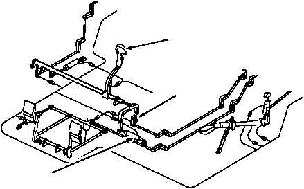
(a) The pilot and CPG cyclic sticks (fig. 11–21) are moved left or right to control lateral movement of the
helicopter.
(b) The lateral LVDTs are located at the base of the pilot’s cyclic stick and CPG’s collective stick. The
pilot and CPG lateral LVDTs monitor cyclic stick movement during DASEC, CAS and BUCS operation. An
electrical signal is developed proportional to cyclic stick movement and sent to the lateral servocylinder to position
the main rotor head.
(c) During normal operation, the SPAD is part of the mechanical linkage. When jamming prevents
normal cyclic lateral stick movement, a force of 30 foot-lbs. on either cyclic stick will cause the SPAD shear pin to
snap, severing the mechanical control linkage which activates BUCS. The BUCS select trigger switch on the
CPG’s collective stick must be closed to activate BUCS. When BUCS is activated, the BUCS ON indicator on the
pilot and CPG caution/warning panels light. When BUCS fails, the BUCS FAIL indicator on the pilot and CPG
master caution/warning panels lights.
CYCLIC STICK
LATERAL SPAD
LATERAL LVDT
M70-261
Figure 11–21.
Cyclic Lateral Control System LVDT and SPAD Assemblies