TM 1-1520-238-T-7
11–62
11–7.
SYSTEM DESCRIPTION (cont)
11–7
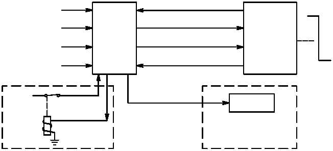
HARS YAW RATE
PILOT LVDT INPUT
DASEC
SAS LVDT FEEDBACK
SAS SOLENOID
COMMAND
LVDT FEEDBACK
DIRECTIONAL
SERVO
TAIL
ROTOR
ASE
CAUTION/WARNING
PANEL
M70-273
YAW
MONITOR
28 VDC
PILOT
ASE
PANEL
SQUAT SW
ADSS AIRSPEED
AND SIDESLIP
Figure 11–35.
SAS/CAS Yaw Functional Block Diagram
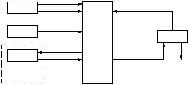
(m) Turn coordination (fig. 11–36) is automatic during yaw SCAS operation when the force trim system is
operating and ADSS airspeed is above 60 knots. Yaw CAS is inoperable during turn coordination operation.
Sideslip signals are sent from the ADSS to the DASEC. Actual sideslip signals are compared to the reference
sideslip and the DASEC computes a command which is sent to the directional servocylinder EHV. The EHV
moves the SAS servocylinder, which changes pitch on the tail rotor blades, correcting sideslip deviations. The
servocylinder provides feedback position to the DASEC. The DASEC then sums the command signals and the
LVDT assembly position signals to null out command signals. This returns the SAS cylinder to a centered position
which stops servocylinder movements.
ADSS
FORCE TRIM
YAW
PILOT
ASE
PANEL
AIRSPEED
SIDESLIP
MONITOR
DASEC
POSITION FEEDBACK
YAW HOLD
DIRECTIONAL
SERVO
TAIL
ROTOR
M70-274
Figure 11–36.
Turn Coordination Functional Block Diagram


