TM 1-1520-238-T-7
11–64
11–7.
SYSTEM DESCRIPTION (cont)
11–7
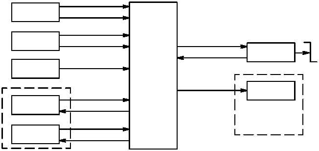
(o) Heading hold (fig. 11–38) operates automatically during yaw SCAS operation. Heading hold mode is
engaged when the ATTD/HOVER HOLD switch on the pilot ASE panel is engaged, force trim is on, and ADSS
airspeed is below 50 knots. The heading hold mode maintains a 1 heading in a 10 to 50 knot wind. Airspeed and
sideslip are sent to the DASEC from the ADSS. Doppler compensated heading reference signals are sent to the
DASEC from the HARS. The actual heading signals are compared to reference heading, and the DASEC
computes a command signal to the directional servocylinder EHV. The EHV moves the SAS cylinder which moves
the servocylinder, correcting heading deviations. The servocylinder SAS LVDT sends position feedback signals to
the DASEC. The DASEC sums the command signal with the LVDT position signal to null out the command signal.
When the command signal is nulled, the SAS cylinder returns to center position and servocylinder movement
stops. Momentary release of the FORCE TRIM switch on the cyclic sticks resynchronizes the rate signal to the
force trim system, establishing a new reference heading. Disengagement or failure lights the ASE indicators on
the pilot and CPG caution/warning panels.
HARS
ADSS
YAW
HEADING
REFERENCE
AIRSPEED
MONITOR
DASEC
POSITION FEEDBACK
YAW HOLD
DIRECTIONAL
SERVO
TAIL
ROTOR
M70-276
TRIM
SIDESLIP
ATTD
HOLD
MONITOR
PILOT ASE PANEL
CAUTION/WARNING
PANEL
ASE
Figure 11–38.
Heading Hold Operation Functional Block Diagram
h. Stabilator Control System (SCS).
(1) Purpose.
The purpose of the SCS is to provide a means to automatically or manually position the
stabilator. The stabilator enhances helicopter characteristics and improves over the nose visibility for landing or
nap-of-earth (NOE) operations.


