TM 1-1520-238-T-7
Change 9
11–65
11–7.
SYSTEM DESCRIPTION (cont)
11–7
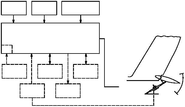
(2) System Operation (fig. 11–39).
(a) The SCS operates in two modes, automatic and manual. Automatic mode is operational when power
is applied to the system. The stabilator cylinder assembly is controlled by the SCU 1 which controls the upper half
(linear cylinder 1), and SCU 2 which controls the bottom half (linear cylinder 2) of the cylinder assembly. Pitch rate
gyros provide an input signal proportional to rate and direction of deviation from the straight and level flight to the
respective SCUs. The ADSS provides input to the SCUs when airspeed is between 30 and 58 knots. Above 58
knots airspeed information is received from the airspeed transducer. When the NOE/APRCH switch on the pilot’s
ASE panel is engaged, the stabilator will drive up to 25 down when airspeed is below 80 knots. The collective
servocylinder LVDT provides continuous position inputs throughout automatic mode operation.
(b) Each SCU monitors itself through a BIT and the SCU condition signal of the other SCU. The SCUs
output system/LRU status to the multiplex bus. If any stabilator component malfunctions or the cylinder positions
differ by more than 10% the automatic mode disengages, the manual mode engages, a warning tone is heard and
the MAN STAB indicator on the pilot and CPG caution/warning panels light. The SCUs compute the desired
stabilator position from input data and compare the computed signal with the actual position signal. Actual
stabilator position is provided from stabilator cylinder assembly feedback. The SCUs then output a signal to the
stabilator cylinder assembly to correct stabilator position. In the automatic mode, the stabilator cylinder assembly
is positioned by SCUs. Positioning is dependent on the pitch rate signal from the respective pitch rate gyro,
airspeed signal and collective stick position. In the manual mode, the stabilator cylinder assembly is positioned by
the stabilator manual control switch NU (nose up) and ND (nose down) positions located on the collective sticks
stabilator manual control panel.
AUTOMATIC
-5º + 3º
0
+25º + 2º
STABILATOR
STABILATOR
ACTUATOR
ASSEMBLY
MULTIPLEX
LINEAR
ADS
AIRSPEED
BIT
PITCH
RATE GYRO
AIRSPEED
XDUCER
COIL
SERVOCYLINDER
LVDT
SCU
SCU
CONDITION
SIGNAL
NOE / APRCH
ENGAGE SW
M70-277
Figure 11–39.
SCU Functional Block Diagram


