TM 1-1520-238-T-7
11–69
11–7.
SYSTEM DESCRIPTION (cont)
11–7
K1-6
K1-3
LIMIT SW 2
EXTEND
MOTOR
LIMIT SW 2
RETRACT
LIMIT SW 1
EXTEND
MOT
MOT
MOTOR
LIMIT SW 1
RETRACT
ASSEMBLY
STABILATOR ACTUATOR
FILTER
RELAYS
MAN
AUTO
K1-1/2
K1-1/2
NC
K1-3/4
SCU 2
SCU 1
NO
NC
NC
K1-3/4
NO
K1-5
K1-3
NC
NC
NO
NO
S
U
B
C
D
G
R
E
M
E
RESET
AUTO
K1-6
RELAY
MAN SEL
K1-3/4
NC
K1-1/2
NC
STAB
MAN
RELAY
AUTO RESET
NC
RELAY
MAN CONT
K1-1/2
NO
K1-3/4
NU
RESET
5
CB52
WARN
ENG
SCU 1
SCU 2
STAB AUTO DC
STAB AUTO AC
RELAY
MAN CONT
K1-5
MANUAL
CONTOL
SWITCH
S
U
B
C
D
1
15
CB6
DC
MAN
STAB
ND
M70-278
FILTER
CONTROL LOGIC
LESS THAN 80 KNOTS = NC
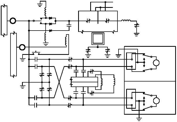
Figure 11–41.
Manual Mode Schematic Diagram
(3) The pilot’s and CPG’s stabilator position (STAB POS) indicators (fig. 11–42) receive power through the
STAB MAN AC circuit breaker (CB7) to transformer T3. Transformer T3 steps down the applied 115 VAC to
26 VAC. When 26 VAC is applied to the STAB POS indicators the OFF flag retracts. The stabilator position
transducer also receives 26 VAC excitation voltage from T3. When the stabilator moves, the transducer develops
a corresponding synchro voltage which is sent to the STAB POS indicators. The synchro signals drive the STAB
POS indicator pointers to indicate the stabilator trailing edge position.