TM 1-1520-238-10
Change 9
2-25
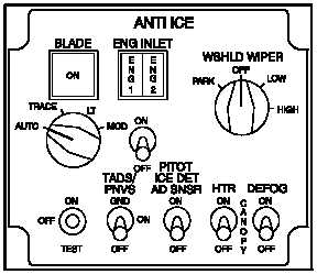
remain continuously illuminated unless the nose gearbox
fairings overheat +121 C (250 F) or under heat 96 C
(205 F) or if the engine inlet section receives anti-ice air
at less than 150 F. If any of these three conditions occur,
the advisory lights extinguish and the ENG ANTI ICE fail
lights illuminate.
M01-143
Figure 2-17.
Pilot/Engine Anti-Ice Panel
2.26 ENGINE FUEL CONTROL SYSTEM.
The engine has a conventional fuel control system: PWR
lever position and the degree of collective pitch basically
establish the power output demands placed on the en-
gines. Engine power is trimmed automatically through in-
teraction of the engine HMU and the ECU
or DECU
. The ECU/DECU of each engine exchanges torque
signals with the opposite engine to achieve automatic
load-sharing between engines.
2.26.1 Fuel Boost Pump.
A low-pressure suction fuel
boost pump is installed on the front face of the engine ac-
cessory gearbox. It ensures that the airframe fuel supply
system is under negative pressure, thus reducing the dan-
ger of fire in case of fuel system damage. If the FUEL PSI
ENG 1 or FUEL PSI ENG 2 segment on the pilot caution/
warning panel illuminates at idle speed and above, it could
indicate a leak or restriction in the helicopter fuel system
or a failed engine boost pump.
2.26.2 Fuel Filter.
A fuel filter is located between the
fuel boost pump and the high-pressure pump in the HMU.
If this filter becomes clogged and impedes the passage of
fuel, a bypass valve permits fuel to bypass the filter. The
differential pressure initiating bypass actuates the fuel-
pressure bypass sensor, thus causing the FUEL BYP
ENG 1 or FUEL BYP ENG 2 segment on the pilot caution/
warning panel to illuminate (fig 2-44). An impending filter
bypass button on the filter housing pops out when filter
element differential pressure indicates impending bypass.
2.26.3 Hydromechanical Unit (HMU).
The HMU pro-
vides metered fuel to the combustor to control the gas
generator (NG) speed. The HMU contains a high pressure
fuel pump to supply fuel to the metering section. The HMU
responds to mechanical inputs from the crewmembers
through the power available spindle (PAS) and the load
demand spindle (LDS). The PAS is mechanically con-
nected to the pilot PWR levers while the LDS is connected
to a bellcrank attached to the collective servo. The HMU
regulates fuel flow and controls positioning of the inlet
guide vanes, variable compressor stage 1 and 2 vanes as
well as the anti-ice and start bleed valve in response to
engine inlet air temperature, compressor discharge air
pressure, NG speed, PAS and LDS positioning, and the
ECU
or DECU
. The torque motor feedback sig-
nals from the HMU to the ECU/DECU are provided by the
linear variable displacement transducer (LVDT) to com-
plete the control activated within the HMU at 100 – 112%
NG speed. The HMU uses signals from the ECU/DECU to
interpret fuel requirements and to vary fuel flow for auto-
matic power control. The HMU will additionally provide NG
overspeed protection in the event the gas generator ex-
ceeds 108 – 112% NG. The reaction of the HMU to an NG
overspeed is the same as for an Np overspeed. Over-
speed protection protects the gas generator turbine from
destructive overspeeds. When an NG overspeed is
sensed, fuel is directed to the MIN pressure valve of the
HMU which causes it to close and shut off fuel to the en-
gine.
2.26.4 Overspeed and Drain Valve (ODV).
The ODV
responds to a signal from the ECU/DECU. Under normal
operation, fuel is routed from the HMU via the oil cooler
and through the ODV to the combustor. When an over-
speed condition is sensed, a signal from the ECU
or
DECU
closes a solenoid in the ODV, thus routing fuel
back into the HMU. All residual fuel is drained overboard.
Fuel flow to the fuel manifold ceases, and the engine
flames out.