TM 1-1520-238-10
2-34
Change 2
Section IV.
FUEL SYSTEM
2.36 FUEL SYSTEM.
The fuel system provides fuel and fuel management provi-
sions (fig 2-22) to operate both engines and the APU. Fuel
is stored in two crash-resistant, self-sealing fuel cells: one
forward and one aft of the ammunition bay (fig 2-23). Fuel
may be transferred from either cell to the other. The sys-
tem is also equipped to crossfeed (select which fuel cell
supplies fuel to the engines). The helicopter has provi-
sions for carrying either two or four external fuel tanks on
the wing pylon attach points. Approved primary fuel
grades and acceptable alternates are listed in Section XV,
table 2-8.
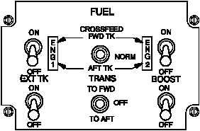
M01-015
PILOT
Figure 2-22.
Pilot Fuel Control Panel
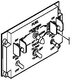
M01-325
PILOT
SWITCH
BARRIER
Figure 2-22.1
Pilot Fuel Control Panel
(Modified)
2.36.1 Pilot Fuel Control Panel. Table 2-1 outlines the
effects of switch settings on the pilot fuel control panel (fig
2-22). Some fuel control panels have been modified with
switch barriers located on the ENG 1 and ENG 2 fuel
switches (fig 2-22.1). The following paragraphs contain a
description of fuel system provisions controlled by the
panel.
a. Fuel Switch.
Two switches, ENG 1 and ENG 2,
control the activation of the crossfeed shutoff valves. In or-
der for fuel to flow to the engines (or crossfeed to the op-
posite engine if selected), the respective fuel switch must
be ON. When in the ON position, the crossfeed switch is
enabled. This controls the positioning of the crossfeed
valve.
WARNING
The crossfeed switch shall be set to
the NORM position at all times, in
flight, unless executing emergency
procedures for FUEL PSI ENG 1 and
FUEL PSI ENG 2 warning advisory. A
malfunctioning crossfeed valve could
result in a single engine flameout.
Do not switch directly from AFT TK to
FWD TK crossfeed (or FWD TK to AFT
TK) without pausing for at least 15
seconds in the NORM position to en-
sure both valves are sequencing to
their proper positions. Failure to fol-
low this procedure may result in a dual
engine flameout if one of the cross-
feed valves fails to properly position.
b. Crossfeed Switch.
This switch simultaneously
controls the position of both crossfeed/shutoff valves.
Three discrete positions, FWD TK, NORM and AFT TK al-
low the pilot to select the fuel cell(s) to feed both engines.
The NORM setting feeds the No. 1 engine from the for-
ward cell and the No. 2 engine from the aft cell. Both en-
gines will feed from either the FWD TK or AFT TK when
selected. This allows the pilot an emergency means to
continue flight to a safe area after sustaining fuel system
damage. The crossfeed switch can still be used on the
ground to control fuel feed during hot refueling. CROSS-
FEED switch must be placed in the NORM position at
least 30 seconds prior to takeoff. If the ENG 1 or ENG 2
fire pull handle is pulled, the


